Top 10 best solder diy kit: Which is the best one in 2018?
When you want to find solder diy kit, you may need to consider between many choices. Finding the best solder diy kit is not an easy task. In this post, we create a very short list about top 10 the best solder diy kit for you. You can check detail product features, product specifications and also our voting for each product. Let’s start with following top 10 solder diy kit:
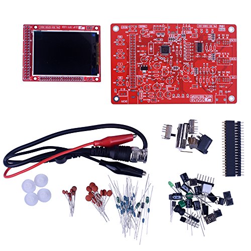


1. Kuman DSO 138 DIY KIT Open Source 2.4" TFT 1Msps Digital Oscilloscope Kit with DIY Parts + Probe 13803K (SMD pre-soldered)
Feature
DSO138 2.4" TFT 1Msps Digital oscilloscope kit for DIYIt's easy to solder.Oscilloscope functions with no fancy features. Simplicity in structure and easiness in assembly
It uses 2.4-inch TFT LCD (320 X 240 dotmatrix, 262K colors) as its display element and displays nice
Detailed assembly instructions are provided in combination with troubleshooting guide and schematc.
Description
Kuman JYE DSO138 is partially open-sourced. This opens the possibility for usersto add different features or develop new applications on the hardware.
DSO138 oscilloscope DIY kit Major features :
Analog bandwidth: 0 - 200KHz
Sampling rate: 1Msps max
Sensitivity: 10mV/Div - 5V/Div
Sensitivity error: < 5%
Vertical resolution: 12-bit
Timebase: 10us/Div - 500s/Div
Record length: 1024 points
Built-in 1KHz/3.3V test signal
Waveform frozen (HOLD) function available
9V DC (8 - 12V acceptable)
Supply Current: 120mA
NOTE: 9V DC power supply required. Not included.
Dimension: 117mm X 76mm X 15mm
Weight: 70 gram (not including cables)
Features
DSO138 kits are sold in two configurations. One is with all SMD parts pre-soldered (PN: 13803K, replacing 13801K).
The other is with only the main IC (the MCU) pre-soldered (PN: 13804K, replacing 13802K).
The latter serves also as a SMD soldering training kit.
For both configurations the MCU has been pre-programmed and no re-programming required.
2. Icstation DIY 3D Christmas Tree Assemble Kit with 7 Color Flashing LED for Electronics Solder Practice
Feature
🎄🎄Creative soldering practice kit with the XMAS tree shape when assembled🎄🎄 7-color 36pcs LED diode make up the flashing light whe power on makes it looks like a small Christmas tree
🎄🎄 DC4.5-5V working voltage can be powered by 3XAA battery or USB power adapter directly(Comes with the battery holder and USB cable)
🎄🎄Assembled Size: 60 X 60 X 136mm/2.36 X 2.36 X 5.35inch(L*W*H)
🎄🎄PDF instruction download link http://attach01.oss-us-west-1.aliyuncs.com/IC/DIY-Manual/7213.pdf
Watch product's vedio via http://attach01.oss-us-west-1.aliyuncs.com/IC/Video/7213.mp4
This assemble kit is cost-efficient for anti-season purchase, and we provide after-sales service, please rest assured to purchase and practice it.
Description
🎄🎄The Christmas is approaching this year, have you already thought of which gift you will buy for your lovely kids, if not, while we suggest you consider this creative 3D christmas tree assemble kit. This is a creative soldering practice kit with the XMAS tree shape when assembled. There are 7-color 36pcs LED diode divided into four groups, and each group has different flashing frequencies, when four groups flash together, it looks like a small Christmas tree, so interesting and exciting. It has 4.5-5V working voltage supporting 3 x AA battery or DC 5V power supply power supply with the battery holder and USB cable.Package Included:
1X 7 Color 3D Christmas Tree Kit
This is a assemble kit that need the user to finish the assemble process.
Download PDF Instruction: http://attach01.oss-us-west-1.aliyuncs.com/IC/DIY-Manual/7213.pdf
Vedio Demo: http://attach01.oss-us-west-1.aliyuncs.com/IC/Video/7213.mp4
http://attach01.oss-us-west-1.aliyuncs.com/IC/Video/7213.gif
After-sales Service:Please be sure to write back if you meet following problems with the order:
* have questions about tracking information.
* need PDF instruction & technical supports.
* received defective item & need replacement. * need more discount for bulk orders.
We will follow up your emails in 12 hours, to make sure that your problems are well solved and that you receive the best customer service. Please rest assure to purchase at ICStation, hope all of our user gains much fun and achievability in testing our products.
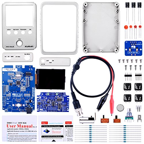
3. Kuman JYE Tech DSO Shell Oscilloscope DIY Kit with Open Source 2.4 inch Color TFT LCD+ Shell + DIY Parts + Probe 15001K (SMD pre-soldered)
Feature
Update From kuman 13803K: The sensitivity of DSO Shell has been extended in both directions and is higher and wider than DSO138. It reaches 5mV/div --- 20V/div while DSO138 is only 10mV/div --- 5V/divMore Applications: Display and MCU are now mounted on the same board (mainboard) to avoid using inter-board pin-headers, Analog channel is placed on a separated board which contains most user install parts. This brings in better separation between analog and digital circuits. Without the analog portion the mainboard can be used in many other applications
Rotary encoder has been added. It makes parameter adjustment much quicker and easier
DSO Shell comes with full enclosure. The front panel and top/bottom brackets are flexible for easy user modification
Detailed assembly instructions are provided in combination with troubleshooting guide and schematic
Description
DSO 15001K is based on JYE DS0 138, More advantages than JYE DS0 138. Applications is larger, parameter adjustment is more quicker and easier and more easy to modify.
Kindly Remind:
DSO Shell runs on 9V (do not use power voltage higher than 10V!)
Power Supply is not included
Specification:
Number of Channel: 1
Analog Bandwidth: 0 - 200KHz
Sensitivity: 5mV/Div - 20V/Div
Sensitivity error: < 5%
Resolution: 12-bit
Input Impedance: 1M ohm
Maximum Input voltage: 50Vpk
Coupling: DC, AC, GND
Trigger Modes: Auto, Normal, Single
Trigger Types: Rising/falling edge
Trigger Position: 1/2 of buffer size fixed
Display: 2.4 inch color TFT LCD with 320 x 240 resolution
Power Supply: 9V DC (8 - 10V acceptable), NOT INCLUDED
Dimension: 115mm X 75mm X 22mm
Weight: 100 gram (not including cables and power supply)
Package Contents:
1* DSO Shell kit with SMD parts on analog board pre-soldered
1* BNC-clip cable
1* Users Manual
4. Longruner DSO138 Open Source 2.4" TFT Digital Oscilloscope Kit 1Msps with Probe Assembled Vision (We (TFT Digital) (Open Source)
Feature
This is Welded(Assembled), can use directly.DSO138 was designed as a training oscilloscope.Circuit is simple , reliable , inexpensive.
With automatic, regular and one-shot mode , easy to capture the moment waveform.
Adjustable vertical displacement, and with instructions.This opens the possibility for users to add different features or develop new applications on the hardware.
This DSO138 MCU has been pre-programmed and no re-programming required.partially open-sourced.
Description
The Longruner DSO138 is full assembled ,not DIY KIT! It contains only the basic oscilloscope functions with no fancy features. Simplicity in structure and easiness in assembly/operation are among the main targets of the design. For these purpose DSO138 uses mostly through-hole parts. The heart of DSO138 is a Cortex-M3 ARM processor (STM32F103C8) from ST. It uses 2.4-inch TFT LCD (320 X 240 dot-matrix, 262K colors) as its display element and displays nice and clear wave forms. Detailed assembly instructions are provided in combination with troubleshooting guide and schematic. Source codes are also available to allow user to add their own features. Features of DSO138: Analog bandwidth: 0 - 200KHz Sampling rate: 1Msps max Sensitivity: 10mV/Div - 5V/Div Sensitivity error: < 5% Vertical resolution: 12-bit Timebase: 10us/Div - 500s/Div Record length: 1024 points Built-in 1KHz/3.3V test signal Waveform frozen (HOLD) function available NOTE: 9V DC power supply required. Not included. Package included: 1 * DSO138 DIY Digital Oscilloscope Kit 1 * Probe 1 * User Manual(English)If you have any question, please be free to contact us, we will try our best to help you. Service Email: [email protected]5. WHDTS 4 Bits Digital Clock Kits with PCB for Soldering Practice Learning Electronics with English Instructions
Feature
The FR-4 PCB board including clear solder joints and components name, it equipped with STC11F02E master chip,easy to assemble and soldering.DC5.5*2.1 power port with 3-6V power supply, come along with a 3.5mm USB power cable, plug in the USB charger to use it.
Accurate travel time, the error range 1 sec every 24 hours. It can be enabled hourly chime; Twice alarm clock setting. Please check the instruction in the description part.
4 digit 0.56" red LED module which is specially for the led clock kit. 24 hour display format.
We are caring each of our customers' experience and ensure each if you is risk- free. Please feel free to contact us if you need any help.
Description
Description:STC11F02E-based of four electronic clock kit
Supply voltage: 3V ~ 6V
PCB Size: 52 x 42mm
Function:
Seconds correction (for precise School)
Switch to every minute independent display interface whole point of time (8-20 o'clock chime can be turned off)
Two alarm settings (you can turn off the alarm function)
Feature:
0.56 inch special red digital clock for display
Import STC11F02E for master chip
1.2mm thick PCB made from military grade FR-4 board
Accurate travel time, travel time error range error -1 to +1 seconds every 24 hours
Package included:
1 x Electronic Clock DIY Kits
1 x Manual
Kindly Reminder:
This produce is DIY kits- not the end product! We don't provide technical assistance please make sure you are familiar with the product before purchasing. Apologize in advance.
Download the material from drive.google.com/open?id=1JOMNnPveEFN3oqbzXZuKXpq9QICQ444x
6. JYE DSO 138 DIY KIT (13801K) Open Source
Feature
AnAnalog bandwidth: 0 - 200KHz. Sampling rate: 1Msps maxSensitivity: 10mV/Div - 5V/Div
Vertical resolution: 12-bit
Timebase: 10us/Div - 500s/Div
Record length: 1024 points
Description
DSO138 was designed as a training oscilloscope kit. It contains only the basical oscilloscope functions with no fancy features. Simplicity in structure and easiness in assembly/operation are among the main targets of the design. For these purpose DSO138 uses mostly through-hole parts. The heart of DSO138 is a Cortex-M3 ARM processor (STM32F103C8) from ST. It uses 2.4-inch TFT LCD (320 X 240 dotmatrix, 262K colors) as its display element and displays nice and clear waveforms. Detailed assembly instructions are provided in combination with troubleshooting guide and schematc. Source codes are also available to allow user to add their own features.This DSO138 kits has all SMD parts pre-soldered (PN: 13801K). The MCU has been pre-programmed and no re-programming required.
DSO138 is partially open-sourced. This opens the possibility for users to add different features or develop new applications on the hardware.
Major features of DSO138:
Analog bandwidth: 0 - 200KHz
Sampling rate: 1Msps max
Sensitivity: 10mV/Div - 5V/Div
Sensitivity error: < 5%
Vertical resolution: 12-bit
Timebase: 10us/Div - 500s/Div
Record length: 1024 points
Built-in 1KHz/3.3V test signal
Waveform frozen (HOLD) function available
NOTE: 9V DC power supply required. Not included.
7. WHDTS D2-5 Smart Car Soldering Project Kits Line Following Robot for Kids DIY Electronics Education School Competition
Feature
Wide - ApplicationSmart robot car is the most widely used in school for helping students to learn about the soldering project knowledge of mechanical structure, electronic basis skills, the principle of sensor, automatic control, soldering skill and so onEasy AssemblyThe operating principle is provided as above picture shown and we provide electronic manual for you. It's much easier to assemble which is great for kids, begginers and hobbyist.
Its PrincipleAs the light reflectivity is difererent when the light is emitting on the white and black items. It uses the photoresistance resistance to tell the smart car is on the right way or not. Smart tracking car can discriminate the direction automatically that it can run freely along the black tracking line.
Design Your RunwayYou can also use the 1.5~2.0 cm black electrical tape directly on the ground to design the complex runway. It would be even more fun!
English ManualWe provide paper English instruction come with the product. You can scan the QR code in the last picture to get PDF manual.
Description
Download the material from drive.google.com/open?id=1kLlV2NlXQeXo56ItreQ1JlUParTRc-16 or just scan QR code on the 7th picture.
1>.Install circuit
1.1 Install metal film resistor,DIP-8P IC socket,Self-Locking switch,Potentiometer,S8550, Capacitor, Red LED on PCB according to mark on PCB
1.2 Install Mecanum wheel
The support bolts of the caster are inserted into the hole, tighten the nuts screwed into the caster, and finally fit the caster and tighten.
1.3 Install photoresistor and white LED on PCB reverse
1.4 Install battery case
1.5 Testing
Install 2pcs AA battery
Press on switch.If 2pcs white LED ON,the installation is successful.If LED off,please check the welding.
2>.Install mechanical parts
2.1 Install the four gaskets on the circuit board
2.2 Insert a steel shaft from the center hole of the wheel and note that the direction is inserted from one side of the raised sleeve of the wheel. It is better to insert the steel shaft parallel to the smooth side of the wheel
2.3 Put a three-way sleeve into the steel shaft, close to the wheel, and then a gasket into the steel shaft, close to the three-way sleeve, installed in place, toggle three-way sleeve, should be flexible.
2.4 Place a gear into the steel shaft in the center of the steel shaft
2.5 Put a three-axis sleeve into the end of the steel shaft so that the car side of the wheel assembly to complete
2.6 Install Motor
3>. Testing
3.1 Power on.Check S8550 or 10ohm resistor if motor don't move
3.2 Install LM393
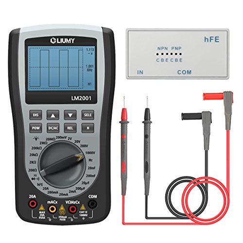
8. Oscilloscope Multimeter, LIUMY Professional Handheld LED Scopemeter Oscilloscope Multimeter with 200ksps A/D Automatic Waveform Capture Function, DC/AC Voltage /Current, Resistance Test with Backlight
Feature
FASTER SAMPLING SPEED -200K SPShigh-seed A/D data collecting, high sampling rate and high bandwidth, one-key transform to waveform function furing measuring.Improve work efficiency.
MORE POWERFUL DETECTION RANGE -
DC voltage 0 ~ 1000V, AC voltage 0 ~ 750V, DC/AC Current 0 ~ 20A, Resistance 0 ~ 20M, Capacitance 0 ~ 20f, Frequency 0 ~ 200KHZ, Diode / Continuity Test, Remote control test, Transistor amplification test to meet all test requirements.
MORE ACCURACY -
Dedicated Chip, the automatic waveform capture function, easy operation. The software calibration technology, memory calibration coefficients. Measure more accurately.
LED BACKLIGHT & STORAGE / READOUT -
Analog broadband range up to: D AC ~ 10kHz, Display hold, storage / readout up to 5 waveforms and 100 sets of measurement values. 128X64 high contrast LCD with LED backlighting. Suitable for working at night.
FUSE PROTECTION & MULTI-PURPOSE -
Built-in 500V/20A explosion proof fuse, 20A AC and DC test. Can choose to automatically shutdown or continuous operation, applicable to the workplace such as family, school, and factory. Protect safety.
Description
Why do you choose us:High-tech chip
LIUMY LM2001 emphasis on functional combination for field testing process, not to replace the meter. It reflects the high-tech, using a dedicated chip has, as the wave function, you can view the waveform signal 10KHZ within.
Extensive detection function and range
Features include DC/AC voltag /current, resistance, capacitance, frequency, diode / continuity test. Can be home, school, power plant, work area has excellent performance!
Save money
As a large number of measuring instruments waveform, you will find LM2001 is the most affordable one, spend the price of a multimeter, you can have a table can be seen, as the wave of the waveform, value for money!
Specification:
Analog Bandwidth: 0~ 10kHz
The maximum real-time sampling rate: 200ksps
DC voltage: 0mV ~ 1000V (0.75% rdg + 10dgt)
AC voltage: 0 mv ~ 750V (1.0% rdg + 10dgt)
DC Current: 0mA ~ 20.00A (1.2% rdg + 10dgt)
AC current: 0mA ~ 20.00A (1.5% rdg + 10dgt)
Resistance: 0W ~ 20.00MW (1.0% rdg + 5dgt)
Capacitance: 0nF ~ 200.0F (2% rdg + 10dgt)
Frequency: 0kHz ~ 200kHz (1.0% rdg + 5dgt),
Diode test: open circuit voltage of about 1.5 V, the maximum test current of about 1.5mA.
Continuity Test: determine resistance: about 30
Remote control Detection: 38kHz carrier frequency
Transistor Magnification: 30 ~ 1000 (annex)
Fuse rating: 5 20,250mA / 250V
Display: 128 * 64 dot-matrix graphic LCD
Battery: 4 x 1.5V AA battery (included)
Storage capacity: DMM 100 groups of data, waveform 5 group records
Dimensions: 186mm * 100 mm * 45mm
Weight: 370g (without other accessories)
Package included:
1 x LIUMY LM2001 Handheld Storage Oscilloscope Multimeter
2 x Test Lead
1 x Portable Bag
1 x hFE tester
1 x English User Manual
4 x 1.5V AA battery
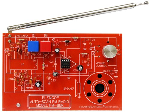
9. Elenco FM Radio Kit
Feature
Build this kit to assemble a monophonic FM receiver (88-108mhz) with electronic auto-scanWill help you understand the basics of working with printed circuit boards
Become familiar with a variety of electronic components
Develop good soldering skills
For 30 years Elenco has been using their strong engineering and design skills to develop reliable, affordable electronic test equipment, tools, and educational kits
Description
Elenco FM Radio KitFrom the Manufacturer This kit is a monophonic FM (frequency modulation) receiver designed to receive FM signals in the frequency range (88-108mhz) it uses electronic auto-scan to search for FM stations. This scan system is done with two button switches-one switch scans up, the other resets to the start of the tuning position.
Manufactured by: Elenco
10. DAOKI C51 4 Bits Digital LED Electronic Clock Production Suite DIY Kits Set
Feature
0.56 inch special red digital clock for displayImport AT89C2051 for master chip
1.2mm thick PCB made from military grade FR-4 board
Accurate travel time, travel time error range error -1 to +1 seconds every 24 hours
Description
Description:AT89C2051-based of four electronic clock kit
Supply voltage: 3V ~ 6V
PCB Size: 52 x 42mm
Function:
Seconds correction (for precise School)
Switch to every minute independent display interface whole point of time (8-20 o'clock chime can be turned off)
Two alarm settings (you can turn off the alarm function)
Feature:
0.56 inch special red digital clock for display
Import AT89C2051 for master chip
1.2mm thick PCB made from military grade FR-4 board
Accurate travel time, travel time error range error -1 to +1 seconds every 24 hours
Package included:
1 x Electronic Clock DIY Kits


Recent Comments